UCS VIC 1340/1380 PCI Placement

I recently did a UCS implementation that included the B460-M4 blades. If you aren’t familiar with these beasts you should look them up. They are two B260 full-width blades connected together with a scalability connector on the front to create one giant server. Each of the B260s had a VIC 1340 MLOM to give the server two VIC 1340s.

download

I did the initial design and configuration consistent with our standard UCS design and logical build out.

We have a standard vNIC/vHBA design for ESXi hosts where there are a minimum of 6 vNICs and 2 vHBAs. The vNICs/vHBAs are split between Fabric A and Fabric b and then map to vSphere vSwitches (Standard and Distributed).

Here is a screen shot of our standard vNIC deign for ESXi on blades with a single VIC

Screen Shot 2016-02-12 at 12.03.17 PM

With two VICs we have a different configuration so that we make use of both VICs. In this configuration we place all of Fabric A vNICs/vHBAs on vCon 1 and all of Fabric B vNICs/vHBAs on vCon 2. With this configuration the vNIC to vmnic numbering changes and so does the vSwitch to vmnic uplinks

Picture1

In this design I implemented this two adapter configuration and built out my templates, pools and policies as usual.

Everything was going well until we built our first ESXi 6 host and couldn’t get management connectivity working. Upon further investigation we realized the vNIC to vmnic mappings were not correct.

After some research I came across this Cisco Bug ID that described our problem to a T – https://quickview.cloudapps.cisco.com/quickview/bug/CSCut78943

I personally wouldn’t call this bug but more of an explanation of the configuration options on the new VICs.

The new VIC 1340/1380s have two PCI channels (1 and 2) and you can control which specific channel the vNIC/vHBA is created on. This new configuration option is called “Admin Host Port” and by default is set to AUTO. With the AUTO setting UCS will round robin each vNIC/vHBA across both Admin Host Ports per vCon.

This Round Robin configuration will place every other vNIC on Admin Host Port 1. This causes an issue because the installed Operating System detects all vNICs on Admin Host Port 1 first and Admin Host Port 2 second.

With the two VICs per blade the configuration that worked like we wanted was to place all of the vNICs on Fabric A on Admin Host Port 1 and the vHBA on Admin Host Port 2 on vCon1 and then the same for Fabric B.

We placed the vHBAs on Admin Host Port 2 so that we could make full use of both PCI lanes.

To configure this on the Service Profile template:

  • Go do the Network tab
  • Click the Modify vNIC/vHBA Placement link
  • Set the placement to Specify Manually
  • Place all Fabric A vNICs/vHBAs on vCon 1
  • Set the Admin Host Port for all vNICs to 1
  • Set the Admin Host Port for the vHBA to 2
  • Place all Fabric B vNICs/vHBAs on vCon 2
  • Set the Admin Host Port for all vNICs to 1
  • Set the Admin Host Port for the vHBA to 2

Here are two screen shots showing this configuration

Picture1

Picture1

Here is a screen shot of the applied configuration, notice all Fabric A vNICs are on the Desired Placement of 1 and Fabric B vNICs on 2. Also notice that the Admin Host Port is 1 for all vNICs.

Picture1


Cisco UCS Director: Part 4 – Workflows

In part 4 of UCS Director I am going to cover the automation features, more specifically workflows. I will also walk you through the process of creating a workflow that automates creating a new VLAN. I will apologize now for the length of this post but most of that is from all of the screen shots I provided. I recommend you click on the screen shots to view them in more detail in a new browser window.

I guess we should start by defining what a a workflow is in the context of UCS Director. A workflow is an organized set of tasks that can be executed to automate simple or complex IT process. This could be something as simple as provisioning a VM to provisioning a new UCS blade.

With UCS Director it is possible to move all of your internal infrastructure administration and provisioning into workflows. By doing this you can achieve better operational and configuration consistency. Another big advantage is that all tasks executed by a workflow are logged in detail and can be rolled back at any time. For example lets say I used a workflow to provision new VMFS storage for vSphere but now I don’t need that data store any more. With UCS Director I don’t have to create a de-provisioning workflow, I can go to the Service Request for when that data store was first provisioned and roll it back.

Another optional task you can easily add to workflows is the Admin Approval task that fires off an email to the user or users specified when the workflow is executed. This could essentially act as your change control approval process where each manager must approve before the tasks in the workflow are executed. The approver also has the option to add comments or reject the workflow with comments on why.

What I like about the automation capabilities of UCS-D is that you don’t have to be a developer or know any scripting to create workflows for automating infrastructure processes. Now if you want and have the development background you can create custom tasks in UCS-D to do almost anything you can dream up.

To access the workflows in UCS Director go to the Policies, Orchestration menu. Workflows are organized into folders and sub-folders, in the below screen shot the workflow folders, Default, NetApp UseCases and System are built-in. The other folders are ones that I have created.

image

UCS Director 5.1 comes with over 1100 built in tasks for managing and provisioning every aspect of the infrastructure elements that can be managed by UCS-D. There are also a lot of pre-built workflows that come with UCS Director, simple tasks like VM provisioning from templates or new VMs from ISO are some of the examples of the built-in workflows.

Here is a screen shot of just some of the built-in workflows that come with UCS Director.

image

Workflows can be exported and imported and shared with others or via this Cisco Communities site – Cisco Developed UCS Integrations

Now that we have went over what a workflow is lets go through the process of creating a workflow. To do this UCS Director provides a very intuitive tool called the Workflow Designer.

Before you jump right in and start creating workflows I highly recommend documenting the processes/tasks you want to automate. If you don’t already have these documented somewhere I would go through test runs of each process you want to automate documenting as you go through it. It is very important that the processes you want to automate are documented so that when you are creating the workflow you don’t miss something. Documenting the processes is also critical for change control.

Here is an example of the processes required to create a new VLAN

image

Before we can edit a workflow with the Workflow Designer we first need to create an empty workflow. To do this click the Add Workflow link on the Workflows tab, this brings up the Add Workflow wizard. The first page of the wizard prompts for basic information like the name, description, folder placement and options like sending the executing user status on workflow execution progress.

image

On the next page, Add User Inputs, I have added two user inputs. These are the inputs required from the user that executes the workflow, in this example the two inputs are VLAN Name and VLAN ID. The type of value for the name is generic text and vlanID for the VLAN ID input type.

image

There are lots of input types for just about anything you can imagine, here is an example of the input types window, notice how small the slider bar is, that should give you an idea of the amount of input types.

image

The next page in the Add Workflow wizard is for optional User Outputs.

image

Both Inputs and Outputs can be either user provided or admin provided and then used as variables in tasks of a workflow.

Now that our workflow is created we can edit it using the Workflow Designer, this can be accessed by either right-clicking the workflow or selecting the workflow and then clicking the workflow designer link on the tool bar.

If you right-click a workflow you also have the option to Clone, Execute, Export, create a new version or display.

image

The workflow designer window looks like this, all available tasks are on the left and the tasks in your workflow are on the right. The pre-configured tasks in all workflows include Start, Completed (Success) and Completed (Failed)

image

The first task we need to add to our workflow is a user approval task, this task is located under Cloupia Tasks, General Tasks or you can type approval in the filer box and it will show you all tasks with the word approval in the name. To add the user approval task select it and then drag it over the the right, when you release it a wizard will open that walks you through configuring the task. The first thing to configure is the name, make your task names are as descriptive as possible and provide a good description. The description is what is visible in the workflow execution service request details.

image

The User Approval task is very basic and requires very little input aside from the user or users you want to send approval to. I am also going to add a second User Approval task for the network admin.

image

Once both User Approval tasks are added I can logically organize them by clicking at the bottom of one task and linking it to the next task. Every task should have both an On Success and On Failure link.

image

It is best that you set the On Failure of each task linked to Completed (Failed) task

image

The next task will be creating the new VLAN on Core switch 1

image

The User Input Mapping page is where the two user inputs come into play, I will select them from the VLAN ID and VLAN Name drop downs.

image

On the Task Inputs page I will admin input the device by selecting it from a list of network switches that were previously added as an infrastructure element.

image

I can also select to save the device configuration or I can do that on a later task

image

For each of the network switches in the DC I will have a Create VLAN task and a corresponding allow VLAN on trunk task.

The finished workflow has 10 individual tasks, here is a screen shot of the full workflow

image

Now lets test it out, Execute the workflow and you are presented with the two user inputs.

image

After I click Submit the service request details window opens where I can monitor the progress and view the detailed log. Until the two approvals are accepted the workflow will pause.

image

If I login as the jwaldrop user and go to Approvals I can see the pending request

image

When I click Approve the service request details open where I can add a comment and then click Approve

image

Now when I go back to the service request details I will see the approval and comment

image

After both users have approved the workflow it continues with creating the VLAN

image

Once the workflow is complete we can check to make sure the new VLAN exists.

Here is one of the Nexus 5548 switches with the new VLAN and the updated trunks where the vlan is allowed.

image

In the accounting log I can see where the ucsd-admin created VLAN 300 and added it to the trunks

image

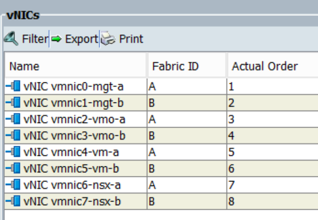
In UCS I can see that the vlan was created and added to the vNIC templates

image

And in vSphere I can see the Add Distributed Port Group task and the new dvPortGroup

image

Take a look at the detailed logging that UCS Director provides, the log tab shows every single change made in detail down to the actual commands executed

image

The Input/Output tab also shows a lot of useful info, if for some reason any task failed I could use this info for troubleshooting

image

Now lets look at the roll back capabilities, lets assume this new VLAN that was created is no longer needed or if you realized that this is the incorrect VLAN ID and you want to undo everything the workflow just did. You are probably thinking that we need to create another workflow to Delete VLAN but since the VLAN was created with a UCS-D workflow we can use the powerful Rollback capabilities.

Under the Organizations, Service Requests menu and I can see all of the workflow service requests.

image

If I right-click on the service request that created VLAN 300 I can choose Rollback Request

image

This opens a window where I can choose to rollback all tasks or just select tasks.

image

Just like the service request to create the VLAN the rollback request also requires admin approval and has the same detailed logging

image

And here is the completed rollback request

image

This was just one example of the types of IT infrastructure processes that can be automated with UCS Director. Other workflows that I have created are:

  1. Zone a new host on the SAN Fabric and present LUNs from an EMC VNX
  2. Create new VMFS LUN on VNX, present it to all ESXi hosts and format the new LUN with VMFS
  3. Create a new VLAN like the one above but this one includes all of the Nexus 1000v tasks
  4. Bare metal provisioning of a new UCS blade, this includes all of the UCS, zoning, SAN Provisioning, ESXi install and vCenter tasks

Here is a screen shot of the workflow to provision a new UCS, ESXi host from bare metal all the way into vCenter.

image

Cisco UCS Director: Part 3

It has been far too long since my last post, no real excuse for it I simply lost motivation to blog.

Since my last post on UCS Director there have been two significant versions released. Review these release notes to see what’s new in each release.

Cisco UCS Director Release Notes, Release 5.0

Cisco UCS Director Release Notes, Release 5.1

One of the nice new features of 5.1 is a Guided Setup tool that provides wizards that walk you through the initial system configuration. The Guided Setup screen automatically opens on login unless you have chosen the option not to display it again. If you do not see the Guided Setup screen you can access it at any time from the Administration, Guided Setup menu.

I highly recommend using the Initial System Configuration wizard to configure licensing, SMTP, DNS and NTP settings.

image

Aside from the Guided Setup there really wasn’t much that changed with regards to the initial installation and configuration since 4.1.

In this post I will go over adding the infrastructure elements that will be managed by UCS Director. For a list of supported infrastructure elements that UCS Director can manage refer to this matrix – Compatibility Matrix for Cisco UCS Director, Release 5.1

In the lab these infrastructure elements will be as follows:

  1. Compute – Cisco UCS B-Series
  2. Storage – EMC VNX 5300
  3. Network Switches – A pair of Nexus 5500s and one Catalyst 3750
  4. Virtualization – VMware vSphere 5.5

Before adding your infrastructure elements there are a few design considerations. UCS Director organizes infrastructure elements into Pods and Pods into sites. This Site and Pod structure must be defined so that when you add each infrastructure element UCS Director knows which pod that element is tied to. The pod definition is also where you tell UCS Director what type of pod and license to expect. The pod types are as follows:

  • FlexPod
  • Generic
  • ExpressPod Medium
  • ExpressPod Small
  • VSPEX
  • Vblock

image

For me this was very simple; one site named Greensboro and one Pod name GSO-LAB.

image

image

The next design consideration is around what user accounts you are going to use to add each infrastructure element to UCS Director. The simplest thing to do is to use the default admin account for each element. There are a couple problems with doing this, one is that you or that elements admin will not be able to look at audit logs to see what changes UCS Director made. The other problem is that if the elements admin wants to restrict UCS Director from managing the device the default admin password has to be changed.

The best practice is to create a UCS Director specific account on each infrastructure element or better yet if each element is using LDAP, RADIUS or TACACS a UCS Director Active Directory account can be leveraged.

Another new feature of UCS Director 5.x are the Credential Policies. I really like this feature because it makes it easier to add like devices and manage the credentials UCS-D uses to communicate with those devices. For example most environments will have multiple network and storage switches with common credentials. For this I can create a credential policy for SSH with the username and password that is common. When I add each network element I can choose the credential policy and not have to key in the same username and password a lot of times.

Before adding infrastructure elements I highly recommend creating a credential policy for the network/storage switches. To do this go to Policies, Physical Infrastructure Policies, Credential Policies menu.

image

In my case I created a new user in each element named ucsd-admin and for simplicity sake set the password the same on each element.

After each infrastructure element had a UCS Director account I added each to UCS Director starting with UCS.

Adding UCS is very straightforward.

  1. Go to Administration, Physical accounts
  2. On the Physical accounts tab click Add
  3. Select the desired Pod, select Computing for the Category and UCSM for account type
  4. Provide the info for IP, login and other optional info

image

image

image

The next account to add is the EMC VNX SAN. This one is bit more involved because for some reason Cisco decided not to include the NaviSecCli command line tool as part of the UCS Director Appliance. NaviSecCli is the only way to manage VNX block from the command line as there isn’t an API or SSH capability for VNX block management. In previous versions of UCS Director the NaviSecCli tool was included with the appliance.

In UCS Director 5.x you must build a Linux VM, install the Linux NaviSecCli tool and then point UCS Director at the Linux VM. It wasn’t very difficult to build a Linux VM with NaviSecCli it was just a big annoyance. Here is a summary of the steps to get this Linux VM built and configured:

  1. Download CentOS 6.4 minimal install ISO
  2. Build a new VM and install CentOS
  3. Download the Linux EMC NaviSecCli RPM and install it on the new VM
  4. Test NaviSecCli from the Linux VM to verify communication with the VNX

Once you have the Linux VM built go to Administration, Physical Account menu and Physical Account tab and click Add.

Select the pod, select Storage for the Category and EMC VNX Block or Unified for type

image

Fill in the required info for the Control Station IP, Storage Processor IPs, NaviSecCli Host IP and credentials.

image

Next go over to the Managed Network Elements tab and add your network and SAN switches. Adding these is very straight forward and this is where the Credential Policies can be leveraged.

image

Lastly add your virtualization platform, this is located under the Administration, Virtual Accounts menu. When you select Add you are presented with this prompt to select your virtualization platform.

image

image

Once all of your infrastructure elements are added go over to the Converged menu to see your Pod with the various infrastructure elements. If you had an environment with multiple Pods you would see all of the Pods listed here or if you had multiple sites you can select the Site from the Site drop-down list.

image

If you select the Pod it will expand to show you each element in more detail

image

From here you can then double-click each element to drill down into the details of that element, view the inventory and even configure.

Here is what the VMware details looks like. The summary tab has some high level utilization reports and connection information. Each one of these individual reports can be added to a custom dashboard tied to your specific UCS Director account.

image

Over on the VM tab if you select a VM and then click on the purple button on the top right you can see all of the configuration options available. Most of what a user can do to a VM in the vSphere Client is available through UCS Director.

image

Another really cool view on the VMware, VM tab is the Stack View that shows you where a specific VM lives on each infrastructure element. This level of visibility across all infrastructure elements in the data center stack is very awesome.

image

Over on the Top 5 Reports tab there are several utilization and performance reports that you ran run on demand

image

The Topology tab is similar to the vSphere Client maps but a bit more useful

image

The Map Reports tab has some very useful heat maps for looking at various resource usage data.

image

All of the other infrastructure elements can be managed, monitored and run reports against similar to vSphere.

With UCS Director it is possible for a company to use it for the management of all of their data center infrastructure instead of managing each infrastructure element individually through their management console.

UCS Director has some great built-in reports and a Report Builder to create custom reports on anything managed by UCS Director. Here is a list of the built-in reports that come with UCS Director.

image

Here is what the UCS Data Center Inventory Report looks like

image

Here is a custom report created with the Report Builder showing the UCS Firmware versions

image

Hopefully my next post will not be 6 months from now but in the very near future. I hope to cover UCS Director Workflows in Part 4.

Cisco UCS Director: Part 2

In Part 1 I went over the features and capabilities of Cisco UCS Director. In part 2 I am going to cover the deployment of the UCS Director Virtual Appliance into a VMware vSphere environment.

The Cisco official installation guide can be found here – http://www.cisco.com/c/en/us/td/docs/unified_computing/ucs/ucs-director/vsphere-install-guide/4-1/b_Installing_UCSDirector_on_vSphere_41.html

Being that UCS Director is distributed via a Virtual Appliance the deployment and initial IP address configuration is very straightforward.

Obliviously before the appliance can be deployed the OVF ZIP must be downloaded from Cisco.

  1. Extract the download ZIP, the download ZIP is around 2.5GB and the OVF/VMDK must be extracted before you can deploy it.
    image
  2. Once extracted you should have 2 files; cucsd_4_1_0_0.ovf and system.vmdk
  3. From the vSphere Client go to the file menu and select Deploy OVF Template…
  4. Browse out to where the cucsd_4_1_0_0.ovf file is located and select it
    image
  5. OVF Template Details
    image
  6. Provide a VM name and inventory location
    image
  7. Select a VM data store
    image
  8. Disk Format
    image
  9. Select the VM network you want the UCS Director in. It isn’t very intuitive but there is a drop-down box in the Destination Networks column. Ignore the warning at the bottom.
    image
  10. Ignore the DCHP warning here, during the first boot of the VM appliance you are prompted for a static IP.
    image
  11. After the VM appliance has finished deploying open the VM console and power it on. During boot you will be prompted to set an IP address.
    image
  12. Once the UCS Director VM appliance is up verify you can ping it and then open a Web Browser to the IP address. The default login is admin, admin
    image
  13. This is what you see on first login
    image
  14. Change the default admin password and create a new user for yourself. To do this go to Administration, Users and Groups
    image
  15. If you have a license upload and apply it under Administration, Licensing
    image

In Part 3 we will get add our infrastructure components and get into the real meat of UCS Director.

Cisco UCS Director: Part 1

Now that I have finally finished up with the CCIE DC I have time to spend on some of the new technology that I have pushed to the side in the last 6 months.

I first heard of UCS Director (Cloupia at the time) about 2 years ago before Cisco acquired them. I was immediately excited about the possibilities this software brings to the table. While I enjoy manually building out new UCS Service Profiles, zoning, provisioning SAN storage and loading ESXi there is something to be said for automating all of those mundane processes.

UCS Director is like having an easy button in UCSM that provisions new compute, storage and networking resources with the click of a button.

Aside from to provisioning automation UCS Director also has extensive management, monitoring and self-service provisioning of physical and virtual servers. Here is are a couple of tables copied from the install guide features list

image

image

Over the next month or so I will be getting UCS Director up on our lab to kick the tires on it. I really think there is a lot of value in this product for a lot of current UCS customers.

My Journey to CCIE Data Center

I am still on cloud nine after passing the CCIE DC lab last week at RTP on my second attempt. This is my first CCIE and this certification means a lot to me. I had started down the path of CCIE RS back in 2010 but I soon realized that without extensive on the job experience working with routing protocols I would never be able pass the lab.

When Cisco announced the CCIE DC certification back in 2012 I knew this one was for me and couldn’t wait until they released the written exam. I didn’t take the beta written exam but as soon it as it was released sometime in late 2012 I took it. I went into the exam over confident and didn’t think I really needed to prepare because I had worked with the technologies since 2009. Well needless to say I failed and learned a valuable lesson. I went back, prepared and knocked it out of the park the second time in May 2013.

After passing the written I was excited to get the lab scheduled ASAP. Little did I know that the lab seat availability was so sparse and had to settle for a date in December. Hind site this was a good thing for me as I wasn’t ready for the lab yet.

On my first attempt last December I was initially a bit over whelmed at the amount of configuration and devices I had to configure. It took me a while to get into a groove and focus. I was constantly looking at the clock and getting panicked that I wouldn’t be able to finish. I was able to get through all of the configuration by around 3:00 but that didn’t leave much time for verification and testing. I left feeling fairly confident that I did enough to pass. Since I took the lab on a Friday I had to wait until Sunday to know the results. I was on pins and needles all weekend and could hardly sleep. I received the email early Sunday morning that the results were posted, I was so nervous it took me a good 30 minutes to get the courage to check. I was so disappointed and defeated when I didn’t pass. 

I wasn’t able to get another seat until mid-March and it was so frustrating having to wait for 4 months. All I could think about was the lab, it was killing me having to wait that long. On my second attempt I had this extreme focus and didn’t hardly come up for air long enough to get a sip of water.

For me the lab was the one of the most mentally stressful days of my life. I walked out of there leaving everything on the table, I have had similar feelings after running ultra marathons. Although those are a bit different because they are a mix of physical and mental stress.

During my second lab attempt I was able to finish all of the configuration by around 1 pm. This gave me plenty of time re-read everything, verify and test. Just like after my first attempt I was so nervous waiting for the results. I didn’t really expect to know anything until the next day so I was shocked to get an email only 3 hours after finishing the lab. I was so nervous, my heart was pounding and it took me a while to get the courage to check the web site. When I saw the word “Pass” I was so excited, I don’t get visibly excited about much but I was jumping up and down excited.

What makes the lab so challenging is that you are presented with this elaborate topology that you have never seen before and are expected to build it out in less than 8 hours. If you were to design and implement such a solution it would be a good 3-4 week project.

Here are some tips for the lab:

  1. It is very important to carefully read and re-read all of the requirements and restrictions. This was something that was very difficult for me as I tend to read too fast and skip over words.
  2. As with most things in technology there is more than one way to do things. In the lab make sure you do every task the way they want it. While it isn’t always clear which way they want it if you read carefully and take into account all of the tasks you will understand which way they are looking for. In the end there is only one way to configure once you take in all of the requirements, restrictions and other tasks.
  3. There are lots of devices to configure on this lab, I am not going say how many but a lot. This makes is very easy to get confused as to which device and interface you are configuring. I was constantly going back to the diagram to verify I as on the correct device and interface.
  4. Do not rely on the provided configuration guides. I am not sure if this is on purpose but I found the navigating the configuration guide menus to be very, very slow. I only needed to verify a couple of things in the config guides but it was very painful.
  5. If you get hung up on a task don’t waste a lot of time trying to troubleshoot it. Move on and come back to it later.

There are no shortcuts to becoming a CCIE. To master all of the technologies in the CCIE DC you must have lots of experience working them. I have been working with most of the technologies on the lab since 2008 and a lot of them I work with on a daily basis.

I would estimate my preparation for the lab consisted of 50% on the job experience, 30% focused practice and 20% reviewing config guides, best practice guides and other various sources. I a very fortunate that I work for such an awesome company (Varrow, Inc.) that has supported in this journey. Being a Cisco partner we were able to acquire most of the hardware tested on in the lab. The only thing we really didn’t have was a pair of Nexus 7000.

For learning and practicing Nexus 7000 features like OTV, VDC and FabricPath I made good use of the Cisco Gold Labs.

I didn’t go to any boot camps or training classes. I learn much better on my own as long as I have access to the gear and documentation.

Since there is not yet a CCIE DC guide out there are several books that I used to help prepare for both the written and lab:

    1. NX-OS and Cisco Nexus Switching-Next-Generation Data Center Architectures
    2. IO Consolidation in the Data Center
    3. Cisco Press – Data Center Fundamentals
    4. Data Center Virtualization Fundamentals Understanding Techniques and Designs
    5. Cisco Unified Computing System (UCS)
    6. Implementing Cisco UCS Solutions
    7. Cisco Storage Networking Cookbook: For NX-OS release 5.2 MDS and Nexus Families of Switches
    8. Then there are all of the Cisco configuration guides that are very dry but very good
    9. There are also a lot of CiscoLive presentation PDFs that are very good. Here is a list of the ones I used:

BRKCOM-2002.pdf, BRKCOM-2005.pdf, BRKCRS-3145.pdf, BRKCRS-3146_1.pdf, BRKDCT-1044_1.pdf
BRKDCT-2048.pdf, BRKDCT-2049.pdf, BRKDCT-2081.pdf, BRKDCT-2121.pdf, BRKDCT-2202.pdf
BRKDCT-2204.pdf, BRKDCT-2237.pdf, BRKDCT-2951.pdf, BRKDCT-3103_1.pdf, BRKRST-2509.pdf
BRKRST-2930.pdf, BRKSAN-2047_1.pdf, BRKSAN-2282.pdf, BRKVIR-3013.pdf

Other resources that I used:

  1. Peter Revill has a great blog with lots of posts on various CCIE DC topics – http://www.ccierants.com/ 
  2. The CCIE DC Facebook groups – https://www.facebook.com/groups/ciscodatacenter/  and  https://www.facebook.com/groups/datacenter.ccie.study/

image                                                           CCIEData_Center_UseLogo

Nexus 5500 FCoE and Jumbo MTU

I happened across an interesting scenario this morning while I was doing configuring jumbo MTU of 9216 on the Nexus 5500 switches in our lab.

I wanted to enable jumbo frames and with Nexus 5500s you have to do this with a QoS policy map. Here are the steps:

  1. Create a new policy map of type network-qos
  2. Add the default network-qos class type of class-default
  3. Configure the MTU to 9216
  4. Add the new policy map to system qos

Continue reading

Cisco UCS Multihop FCoE QoS Gotcha

See my post on configuration and migration to multihop FCoE for details on my lab setup – https://jeremywaldrop.wordpress.com/2013/04/11/cisco-ucs-fcoe-multihop-configuration-and-migration/

When I first configured UCS multihop FCoE I experienced terrible SAN performance. It was so bad that it took 20 minutes to boot a single virtual machine.

Continue reading

Nexus 5500 SAN Admin RBAC

It’s been a while since I have posted anything on my blog. I just haven’t had the motivation to do it.

The current unified fabric project I am working on and the newly released CCIE DC has sparked a renewed interest in digging deeper into NX-OS.

As I stated above I am working on a unified fabric project where the customer is using a pair of Nexus 5596s for both 10G server access and SAN FC switching for host HBAs and SAN connectivity.

Continue reading

Custom ESXi 5 ISO for UCS, Nexus 1000v and PowerPath VE

With ESXi 5 VMware made it very easy to create custom installation ISOs. I have been doing a lot of upgrades from ESXi 4.1 in our customer sites that have UCS, Nexus 1000v and PowerPath VE so I decided to create a custom ISO that includes the current UCS enic/fnic drivers and Nexus 1000v/PowerPath VE.

When I first started doing these upgrades I would remove the host from the Nexus 1000v VDS, uninstall Nexus 1000v VEM and uninstall PowerPath VE. After upgrading/rebuilding the host I would then use VUM to install Nexus 1000v VEM add it back to the VDS and then install PowerPath VE.

Continue reading